Voltage Level Detector Meaning
Voltage Level Detector Circuit Working Circuit Diagram Simulation

Op Amp Comparator And The Op Amp Comparator Circuit
3 Simple Battery Voltage Monitor Circuits Homemade Circuit Projects

Voltage Sensor Working Principle Types Circuit Diagram Electrical4u

Window Detector Wikipedia
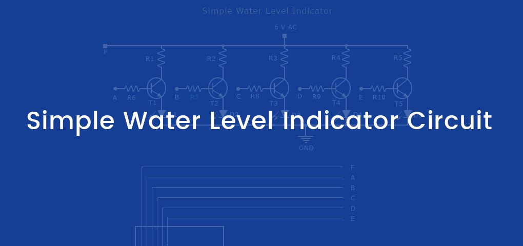
Simple Water Level Indicator Circuits With Images Homemade Circuit Projects
It can be a simple pen shaped piece of testing hardware that indicates the existence of electricity or an advanced tool that detects precise voltage levels in electrical systems.
Voltage level detector meaning.

What Is A Voltage Detector
Op Amp Tutorial 2 Features Of Inverting And Non Inverting Input And Application

Simple 12v Battery Status Indicator Circuit Diagram Electronics Circuit Circuit Diagram Battery Charger Circuit

Difference Between Voltage Signal Systems Current Signal Systems Instrumentation And Control Engineering
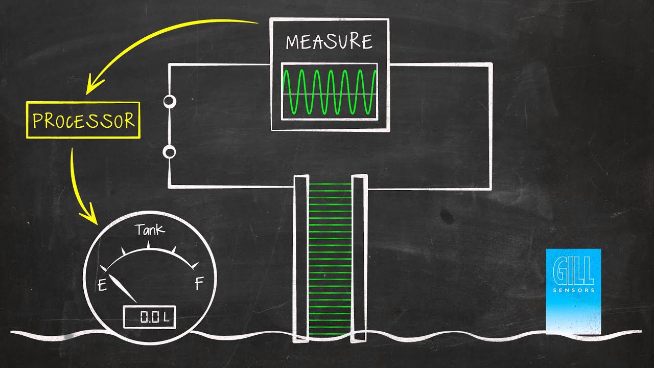
How Does Capacitive Level Sensing Work Gill Sensors Controls
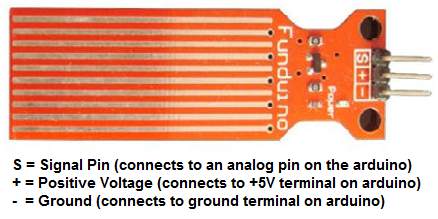
How To Build A Liquid Level Indicator Circuit With An Arduino

Voltage Divider And Voltage Division
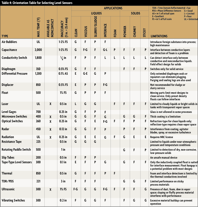
Liquid Level Sensors Selection Guide Engineering360

2 Battery Level Indicator Make Easily At Home Youtube Electronic Schematics Electronic Circuit Projects Smartphone Repair
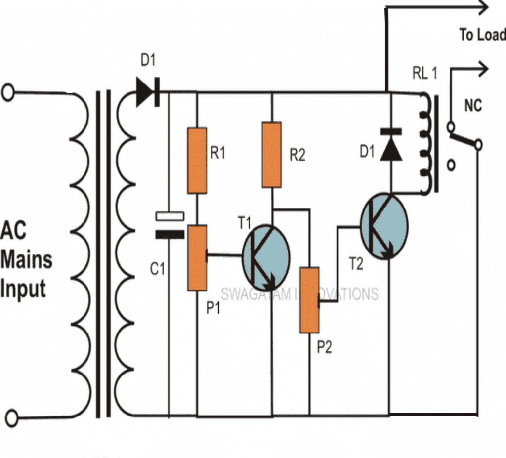
3 Tested 220v High And Low Voltage Cut Off Circuits Using Ic 324 And Transistors Homemade Circuit Projects

Wheatstone Bridge Circuit And Theory Of Operation

The Basics Of Vlf Testing Hv Technologies Inc
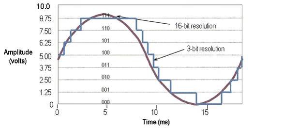
How To Choose The Right Daq Hardware For Your Measurement System Ni
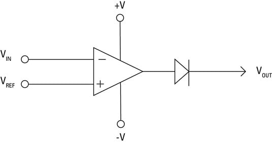
Electronics Components How To Use An Op Amp As A Voltage Comparator Dummies

Water Level Indicator What How Types Purpose Benefits

Practical Troubleshooting Of Electronic Circuits For Engineers And Technicians

Infrared Motion Detector Circuit Circuit Diagram Working Applications Motion Detector Circuit Diagram Electrical Circuit Diagram

How To Build Simple Mains Voltage Protection Circuits Low Voltage Indicator Circuit High Voltage Detector Circuit Circuit Home Protection Electrical Projects
Https Encrypted Tbn0 Gstatic Com Images Q Tbn 3aand9gcrxmjstbpkea4ugdjhkfmp9kytlv Wfmospntjafg9o 4fqqax0 Usqp Cau

Simple Water Level Indicator With Alarm 3 Tested Circuits Circuit Simple Circuit Circuit Design

Tl431 Internal Circuit Diagram Circuit Diagram Circuit Diodes

Pin On Me
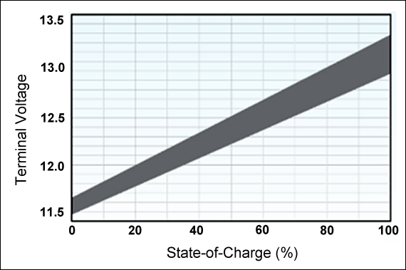
Measuring State Of Charge Battery University
Op Amp Comparator Circuit Working And Its Applications

Senzor Detekcie Hladiny Tekutiny Riadiaca Jednotka Snimac Hladiny Vody Nizky Tlak Water Level Switch Electronic Circuit Projects Sensor

Level Sensor An Overview Sciencedirect Topics

Water Level Sensor Circuit

Active And Passive Instruments Instrumentation And Control Engineering

Measurement And Control Of Rf Power Part I Analog Devices

24v Battery Level Indicator

3 7 Volts Battery Low And Full Level In 2020 Electronics Mini Projects Electronics Circuit Electronic Circuit Projects
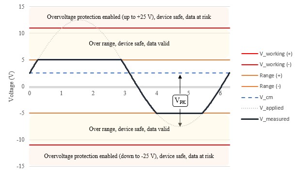
Specifications Explained Ni Multifunction I O Mio Daq Ni

Pin On Scheme Electronice

In Depth How Water Level Sensor Works And Interface It With Arduino Last Minute Engineers

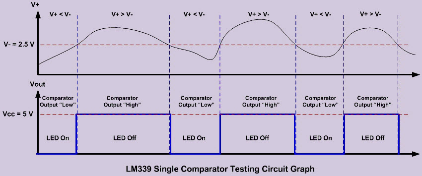
Lm339 Quad Op Amp Pinout Electronics Basics Electronics Circuit Circuit

Photocell An Overview Sciencedirect Topics
Jhsv Yoohrakfm

Lp2985 Application Circuit In 2020 Voltage Regulator Dropout Regulators

74hc73a Jk Flip Flop Circuit Diagram Flip Flops Flipping Circuit Diagram
Water Level Indicator Circuit Diagram Liquid Level Sensor Project

Gravity Photoelectric Arduino Water Liquid Level Sensor Dfrobot
High Voltage Connector Types Design Issues Arrow Com
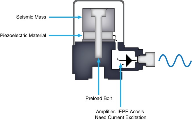
Measuring Vibration With Accelerometers Ni
Https Encrypted Tbn0 Gstatic Com Images Q Tbn 3aand9gcs2qq1xqswqovgxwsluvv62w0t2i9tygrvbsi59c1ahyqyqex1b Usqp Cau
Source : pinterest.com
