Variable Rf Attenuator Circuit
Variable Pin Diode Attenuator Daycounter

Rf Attenuators Digikey

Schematics Com Low Insertion Loss Voltage Variable Attenuator Circuit

Bridged T Attenuator Tutorial For Passive Attenuators

Potentiometer Is A Three Terminal Variable Resistor Which Acts As An Adjustable Voltage Divider It Is Used I Voltage Divider Electronics Circuit Circuitry

Diode Quad Is Foundation For Pin Diode Attenuator Microwaves Rf
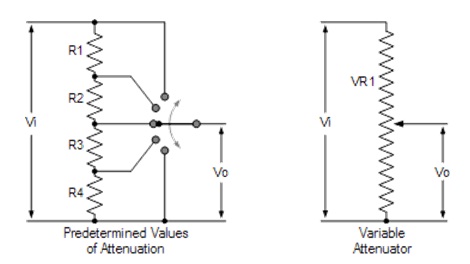
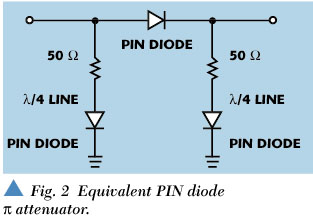
Pin diode attenuators are a subset of variable rf attenuators and are useful for circuits requiring continuously changing attenuation levels.
Variable rf attenuator circuit.

Colpitts Lcoscillator Is An Electronic Circuit That Produces A Periodic Oscillating Electronic Si Electronics Circuit Electronics Projects Electric Circuit

Waveguide Shorting Plates Provide An Almost Perfect Rf Reflection In A Waveguide System Electronics Collection Of L Electronics Projects Electronics Reflection

The Depletion Mode Has Negative Gate Operation This Decreases The Width Of The Depletionlayer Electronics Circuit Depletion Region Electronics

Schematics Com Search Results

Price Power And Size Drive Attenuator Advancement Microwaves Rf

Microwaves101 Variable Attenuators

Application Note Variable Attenuators

Rf Attenuator Basics Rf Attenuator Manufacturers Vendors

A Transistor Based Computer Circuit Electronics Circuit Transistors Circuit

Designing With The Hmc346ms8g Voltage Variable Attenuator Eeweb

Variable Attenuator Blends Dynamic Range Linearity Microwaves Rf

Pin On Electronics Projects

Awr Visual System Simulator System Block Catalog Variable Digital Step Attenuator Dsatten Var

Pdf Variable Attenuator Blends Dynamic Range Linearity

Jeu D Icones De Symbole Electrique Symboler Teknik

Pin Di Clamshell Screw Fiber Optic Fast Connector Sc Lc Fc
Attenuator Design Different Types Its Applications

Infrared Emitter 38khz 555 Timer Circuit Schematic Electronics Circuit Timer Infrared

Pin By Robertt On Infographs Electronic Schematics Electrical Circuit Diagram Electronics Components

Pin On Other Consumer Electronics Consumer Electronics

Figure 10 From Highly Linear Rf Cmos Variable Attenuators With Adaptive Body Biasing Semantic Scholar

And The Resistor Color Strength Goes B B R O Y G B V G W Just In Case You Didn T Ha Electronic Engineering Electronics Basics Electronic Schematics

Audio Limiter Circuit Electronics Circuit Audio Amplifier Circuit
Voltage Controlled Variable Gain Amplifier Electronic Circuit Diagram

100w N Type Rf Coaxial Fixed Attenuator 50db Dc 3ghz Free Shopping Free Shopping Electrical Equipment Electronic Products
A Voltage Variable Attenuator Using Silicon Pin Diodes And A Passive Gaas Mmic In A Plastic Smt Package

Alan 50v70 Sma Coaxial Step Attenuator With Images Ebay Coding Flask

Pin On Electronics

Bass Guitar Preamp Kit Bass Guitar Diy Guitar Pedal Guitar

Pdf A Pin Diode Controlled Variable Attenuator Using A 0 Db Branch Line Coupler
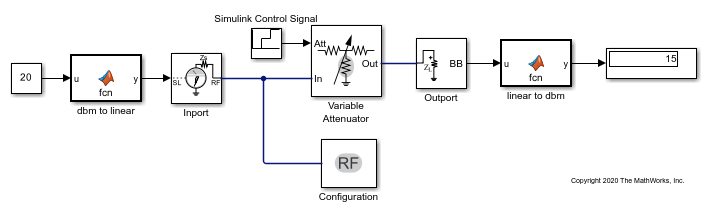
Model Variable Attenuator Simulink

Figure 7 From A Broadband Low Reflection Electronically Variable Pin Diode Based Attenuator Semantic Scholar

Pin On Aliexpress New

Idea De Electrical Symbols En Electrical Electronic Symbols

Autotransformer And Variable Auto Transformer

X Amp A New 45 Db 500 Mhz Variable Gain Amplifier Vga Simplifies Adaptive Receiver Designs Analog Devices

Chapter 7 Diode Application Topics Analog Devices Wiki
Variable Amplifier Impedance

Circuit October 2010

Buffer Circuits An Overview Sciencedirect Topics
Https Ieeexplore Ieee Org Iel7 8700146 8701725 08701778 Pdf

Microwave Waveguide Attenuator Waveguide Attenuator Manufacturer

Demo Board Accessories Ad8367 Agc Voltage Gain Block High Performance Variable Gain Amplifier Wide Bandwidth Detector In 2020 Detector Amplifier High Performance

0 30v Variable Power Supply Circuit Diagram At 3a Eleccircuit Com Power Supply Circuit Circuit Diagram Electronic Circuit Projects
Source : pinterest.com
